
The FREESCALE MMA7361 is a three axis accelerometer with selectable sensitivities of +/- 1.5g or +/- 6g. With the range set to 1.5g, the sensitivity is 800 mV/g and with the range set to 6g, the sensitivity is 206 mV/g. The device features a micromachined capacitive sensing cell along with a built in signal conditioning circuit.
The sensing cell is formed from polysilicon semiconductor materials and each axis can be thought of as a beam attached to a central mass that moves between two fixed beams. The moveable beam is displaced from the rest position when subjected to acceleration. This change in distance between the fixed beams and moveable beam is proportional to the acceleration force.
The beams form two back to back capacitors and switched capacitor techniques are used to determine the acceleration force from the difference in value between the two capacitors. The output from the conditioning circuit on each axis is a DC voltage proportional to the acceleration force.
 |
| CLICK ON FOR LARGER IMAGE |
The MMA7361 operates with a supply voltage of 3.3VDC. The typical voltage output from the x, y, and z axis under static acceleration conditions is 2.45V (+1g) to 0.85V (-1g).
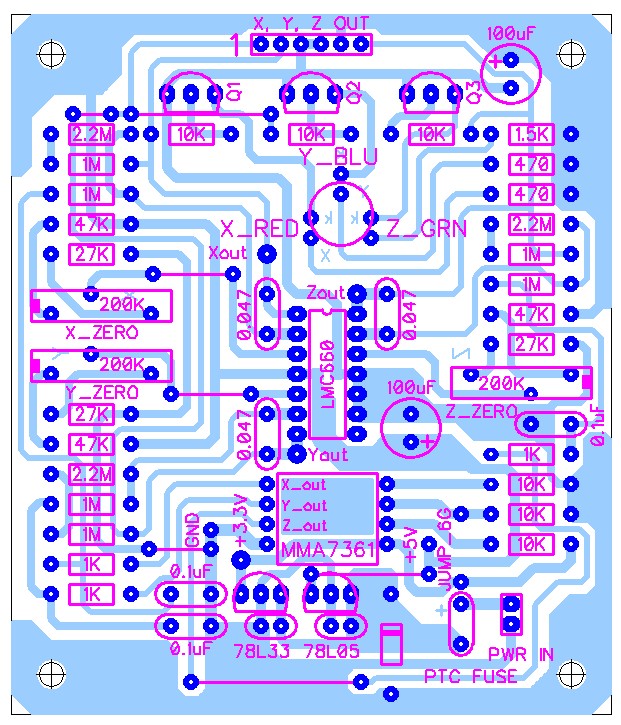
To increase the sensitivity when interfacing the MMA7361 to a microcontroller operating at 5 volts, an OpAmp circuit (shown below) can be used to scale the accelerometer output from 5mV at +1g to 4.5V at -1g. Note that the output is inverted from normal.
The circuit also has three optional LED’s to indicate the change in output voltage from the x, y, and z axis. These LED’s make it easy to visually see the change in “g” forces as the accelerometer is moved about on each axis.
Since the board is primarily through-hole construction, a small SMT carrier board was created for the MMA7361 and connected to the amplifier PCB using two 0.1" pin headers.
The "zero" point for each axis can be adjusted using a 200K potentiometer. The gain is fixed using two resistors in series. Using two resistors allows trimming the gain a bit easier since different values can be combined to achieve a needed resistance and also is cheaper than adding another potentiometer.
The op-amp is a NATIONAL LMC660 CMOS quad amplifier with rail to rail output. It works well with single power supplies between +5 and +15 VDC.
ACCELEROMETER SCHEMATIC
 |
| CLICK ON FOR LARGER IMAGE |
 |
| CLICK ON FOR LARGER IMAGE |
This photo shows the finished PCB with the three X, Y and Z AXIS LED’s lit. This was accomplished by adjusting each of the three “zero” adjustment potentiometers, with the PCB in a static (level) position, until the axis LED just became lit.

This photo shows the PCB tipped up slightly to a diagonal position. The X (RED) and Y (BLUE) axis LED’s are now off indicating a response to the change in position. Having the “zero” potentiometers allows calibrating the output of the MMA7361 to specific baseline value.

SMALL ACCELEROMETER PCB
This is a similar but much smaller PCB that amplifies and scales the X axis and either the Y or Z axis (jumper selected). The board measures 1.1in by 2.2in and uses a combination of surface mount components and through-hole 0.125w resistors. The use of through-hole resistors allowed routing traces under the resistors and let me route all the traces on one side of the board. The board requires +5VDC input. A 3.3VDC SMT regulator powers the MMA7361. The two trim pots allow adjusting the axis output center point (usually 2.5VDC) or calibrating the output to the position of the PCB.

