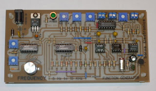
This function generator features a tuning range of 5 Hz to 15 KHz and has SINE, SQUARE and TRIANGLE outputs. The circuit is based on a 555 timer operating as a Schmitt trigger. A CA3140 is used as a voltage follower to “read” the voltage across the timing capacitor. The CA3140 also drives the 555 and provides the triangle output. The triangle waveform is created from the charge and discharge of the timing capacitor from the constant current provided by a CA3080 operational transconductance amplifier (OTA). The square wave output comes directly from pin 3 (output) of the 555 timer.
The frequency is adjusted by a 1k pot along with a LM3046 transistor array used as an adjustable current source feeding the OTA. There is also a “HI CAL” pot and a “LOW CAL” pot to set the upper and lower frequency limits.
The SINE output uses another LM3046 that functions as a triangle to sine wave converter. There are also two trim pots that are used together to null the output distortion to 0.3% of less.
Both the TRIANGLE and SINE outputs are buffered by an LM3900 with the output adjustable from approximately 5V to 15V.
Finally, an LED is connected to the SQUARE wave output to provide a visual indicator.
The PCB measures 3.0in by 6.0in and made of 0.032in glass epoxy.
I know that there are single chip function generator IC’s available that does essentially the same thing as this. However, this design was more challenging and is easier to customize for a specific application.
Additional information about this design can be obtained from “THE IC TIMER COOKBOOK” by Walter Jung. Published in 1977 by Sams Publications.
PCB ASSEMBLY
PCB LAYOUT
10KHZ SINE OUTPUT
1KHZ TRIANGLE OUTPUT


No comments:
Post a Comment